|
|
- Technical Information
- Function of tool features for face milling
- Corner angle and tool life
FUNCTION OF TOOL FEATURES FOR FACE MILLING
CORNER ANGLE AND TOOL LIFE
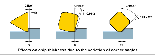
Corner angle and chip thickness
When the depth of cut and feed per tooth, fz, are fi xed, the larger the corner angle (CH) is, then the thinner the chip thickness (h) becomes (for a 45° CH, it is approx. 75% that of a 0° CH). Therefore as the CH increases, the cutting resistance decreases resulting in longer tool life.
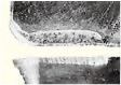
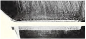
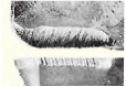
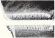
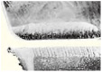
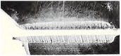
Corner angle and crater wear
The table below shows wear patterns for different corner angles. When comparing crater wear for 0° and 45° corner angles, it can be clearly seen that the crater wear for 0° corner angle is larger. This is because if the chip thickness is relatively large, the cutting resistance increases and so promotes crater wear. As the crater develops then cutting edge strength will reduce and lead to fracturing.
| Corner Angle 0° | Corner Angle 15° | Corner Angle 45° | |
|---|---|---|---|
| vc=100m/min Tc=69min |
 |
 |
 |
| vc=125m/min Tc=55min |
 |
 |
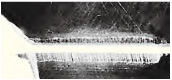 |
| vc=160m/min Tc=31min |
 |
 |
 |
- Workpiece :
- Alloy steel (287HB)
- Tools :
- D1=125
- Insert :
- M20Cemented Carbide
- Cutting Conditions :
- ap=3.0mm
ae=110m
fz=0.2m/tooth - Dry Cutting